Description
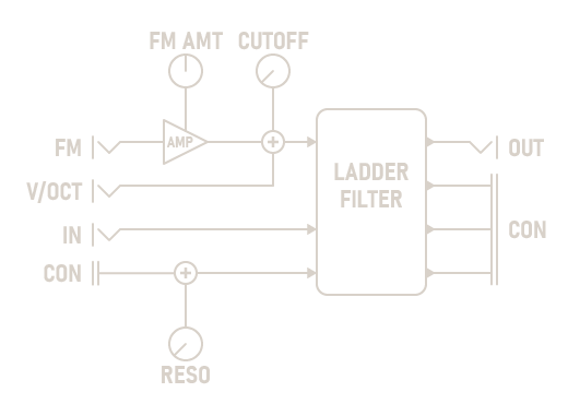
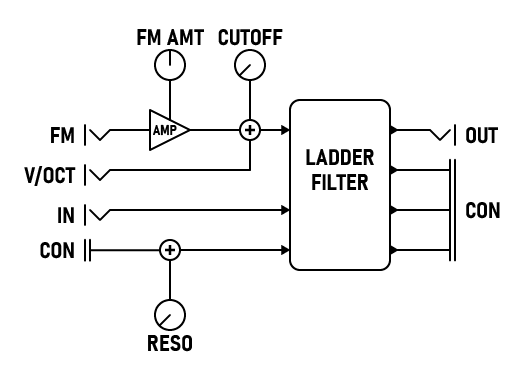
The LP4 Filter is a non-linear four-pole low-pass filter with 24 dB per octave attenuation. It can dynamically shape sounds and pick out individual harmonics, or act as a sine oscillator.
For additional functionality, add a Filter+ to either side of this module. If two expanders are present, their inputs are summed and their outputs are duplicated.
Parameters
-
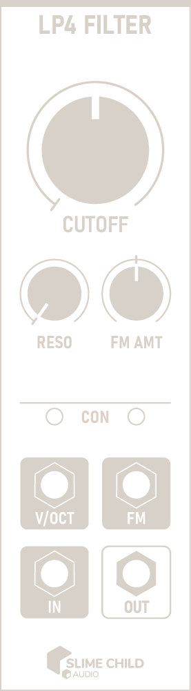
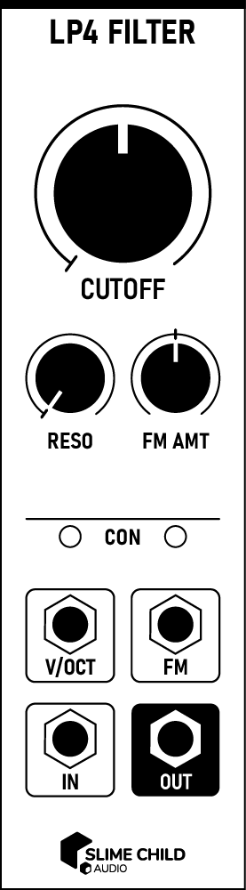
CUTOFF Knob
Sets the filter's cutoff frequency, from 20 Hz to 20k Hz. Increasing the cutoff results in a bright and buzzy sound, while decreasing it results in a dark and thick sound.
When using the filter as a sine oscillator, set this knob to 261.63 Hz (Middle C) and use the V/OCT input to change the pitch.
-
RESO Knob
Sets the filter's resonance, from 0% to 120%. Increasing the resonance allows some of the filter's output to be shaped and routed back to the input. This creates a resonant peak that emphasizes the cutoff frequency.
Pushing the resonance beyond 100% causes the filter to self-oscillate, producing a pure sine tone at the cutoff frequency. In some cases, it can also create "half-harmonics" that lie between an input signal's existing harmonics.
-
FM AMT Knob
Modulates the effect of the FM input, from -100% to +100%.
At 0%, FM has no effect. At +100%, FM's value is added to IN. At -100%, its value is subtracted.
Ports
-
V/OCT Polyphonic Input
Accepts a 1-volt/octave control signal that sets the filter cutoff. The CUTOFF knob sets the frequency corresponding to 0V.
V/OCT INPUT: -5V to +5V
-
FM Polyphonic Input
Modifies the filter's cutoff frequency. Connect the FM input to one of the ENV outputs on Envelopes to shape sounds, or to an LFO to slowly modulate the cutoff frequency.
CV INPUT: -5V to +5V
Note: Value is added to V/OCT after passing through FM AMT; exponential response.
-
IN Polyphonic Input
The input signal.
AUDIO INPUT: -5V to +5V
-
OUT Polyphonic Output
The output signal after passing through the filter.
AUDIO OUTPUT: -5V to +5V
Context Menu
Context menu options can be accessed by right-clicking on the module.
-
Quality
Configure the filter quality level, between Default, High, and Extreme. When self-modulating resonance or cutoff, a higher quality level can help reduce distortion. In most cases, the difference between these levels is not audible, and this setting can be left at Default. Note that higher quality levels will use more CPU. -
Add expander (right, 4HP)
Adds an instance of Filter+ to the right of this module.