Slime Child Audio is still alive!

Thank you for purchasing Substation for VCV Rack! We're so excited to see what you make.

Substation relies on two fundamental concepts: polyrhythm and subharmonics.

About Polyrhythm

Let's start with polyrhythm. Polyrhythms are created when two or more rhythms overlap and play at once, creating a more complex, rhythmically interwoven phrase. These rhythms are still cyclic, but repeat over longer periods: for example, if divisions 3 and 4 are combined, the resultant polyrhythm will be 12 steps long.

In order to create polyrhythms, the PolyRhythm Sequencer combines up to four distinct clock divisions to create a new rhythm. Because all the clock dividers reference the same clock, they remain synced with the rest of your patch. For added complexity while performing, you can change the logic used to combine rhythms or alter the divisions on the fly.

Clock
÷3 – – – – – – – –
÷4 – – – – – – – – –
OR – – – – – –
XOR – – – – – – – –

About Subharmonics

Now that we've discussed polyrhythms, what are subharmonics? Before we talk about subharmonics, we first need to discuss overtones.

When physical instruments play notes, they generate additional tones at whole number multiples of the note's frequency. These are created by the way that sound waves move through physical materials. For example, a piano playing an A4 at 440 Hz will also create tones at 880 Hz, 1320 Hz, 1760 Hz etc. These are called overtones, or harmonics after the harmonic sequence in math.

The relative volume of these overtones is one of the main factors that determines the timbre of an instrument, and it is by manipulating overtones that filters can shape sounds. These overtones are especially welcome when playing chords, since they interact across notes and fill out the sound.

Subharmonics on the other hand, are created with whole number divisions of frequencies instead of multiples. They are difficult to create with physical instruments, but can be modelled electronically. Like overtones, subharmonics change the timbre of a sound, filling it out and making chords sound richer.

Substation uses subharmonics and overtones together to create rich, moving chords. It can also use subharmonics to self-modulate its oscillators, creating fractional multiples that sound wholly unique.

Overtone Interval Octave
×1 — —
×2 Unison Up +1
×3 Perfect Fifth Up +1
×4 Unison Up +2
×5 Major Third Up +2
×6 Perfect Fifth Up +2
×7 Subminor Seventh Up +2
×8 Unison Up +3
Subharmonic Interval Octave
÷1 — —
÷2 Unison Down -1
÷3 Perfect Fifth Down -2
÷4 Unison Down -2
÷5 Major Third Down -2
÷6 Perfect Fifth Down -2
÷7 Subminor Seventh Down -2
÷8 Unison Down -3
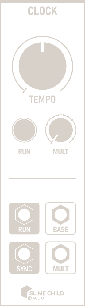
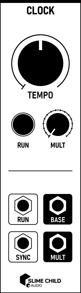
Clock Outline Clock Outline

Description

The Clock module generates regular pulses that can drive the Polyrhythm Sequencer or any other clocked module.

Parameters

  • TEMPO Knob

    This knob sets the base tempo from 20 BPM to 720 BPM or 0.33 Hz to 12 Hz.

  • RUN Button

    This button is used to start or stop the clock. When the RUN port is connected, the button automatically changes state to reflect it.

    The spacebar can also be used to quickly start or stop the clock.

  • MULT Knob

    This knob is used to generate a secondary, synced clock pulse at rate equal to the product of TEMPO and MULT. This is useful when clocking multiple modules: because the Polyrhythm Sequencer divides the clock rate, it is helpful to provide it a faster rate than other modules in a patch.

Ports

  • RUN Input

    Signal transitions received here toggle the status of the RUN button. A rising edge starts the clock, and a falling edge stops it. Pressing the button manually overrides the status.

    GATE INPUT: 0V to +10V (rising edge, falling edge)

    Note: Unlike other clock modules, gate value is not important; only transitions (rising, falling edges) toggle the clock status.

  • SYNC Input

    A rising edge received here re-syncs the clock. Following a sync, both BASE and MULT reset to the beginning of a full pulse, starting HIGH.

    This port is useful for syncing to other external clock modules. As long as the module receiving sync pulses has a tempo equal to or greater than the rate of incoming pulses, output pulses are synchronized.

    TRIGGER INPUT: 0V to +10V (rising edge)

  • BASE Output

    Clock pulses are output here at the un-multiplied tempo.

    CLOCK OUTPUT: 0V to +10V

  • MULT Output

    Clock pulses are output here at the multiplied tempo.

    CLOCK OUTPUT: 0V to +10V

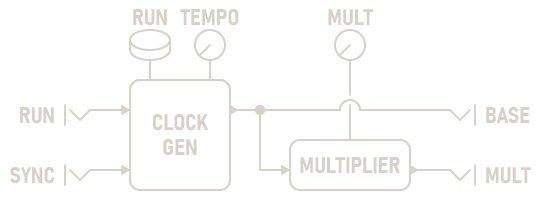
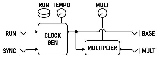
Signal Flow Diagram

Clock Diagram Clock Diagram
PolyRhythm Sequencer Outline PolyRhythm Sequencer Outline

Description

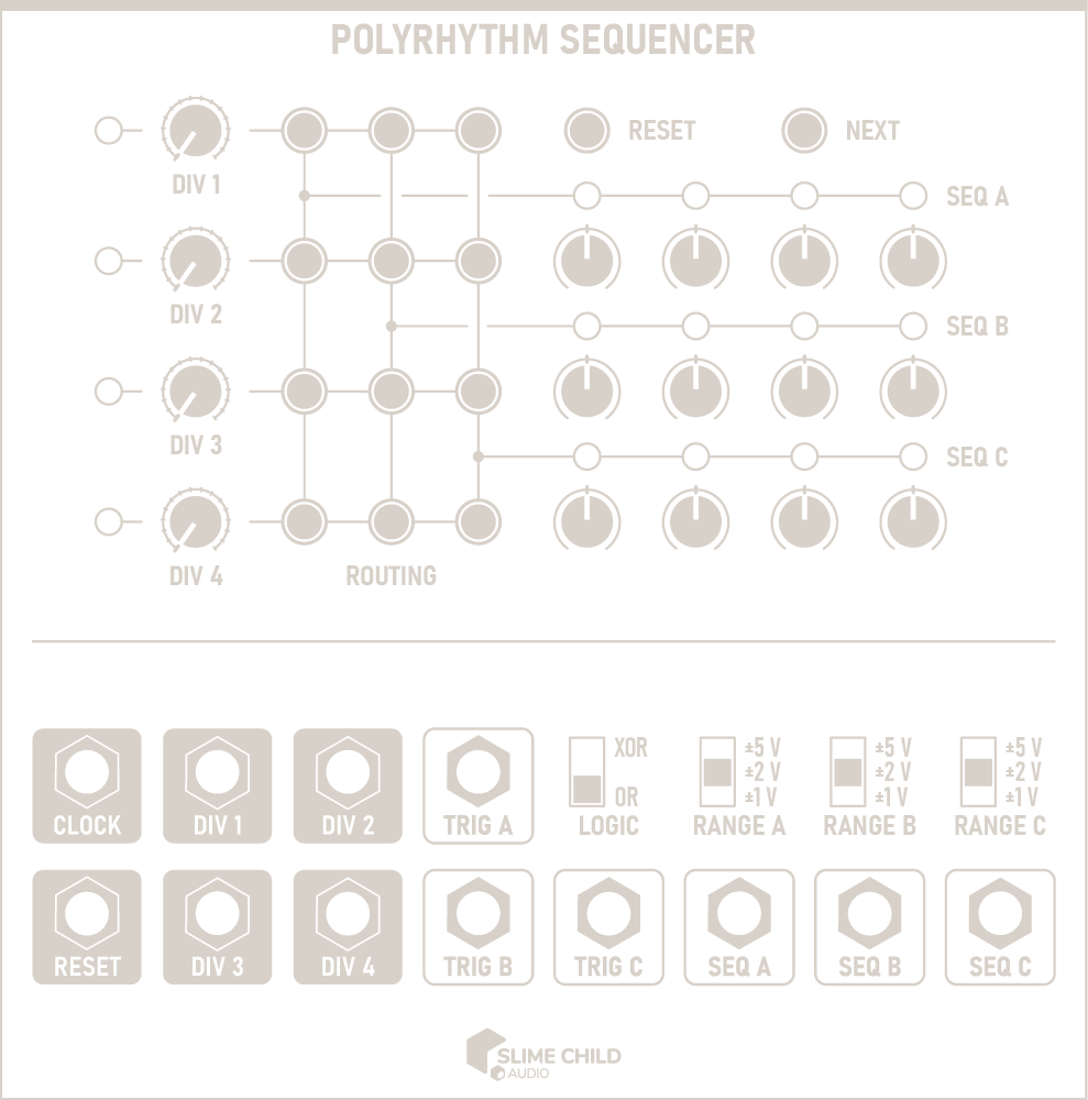
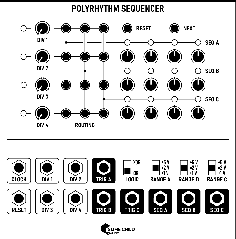
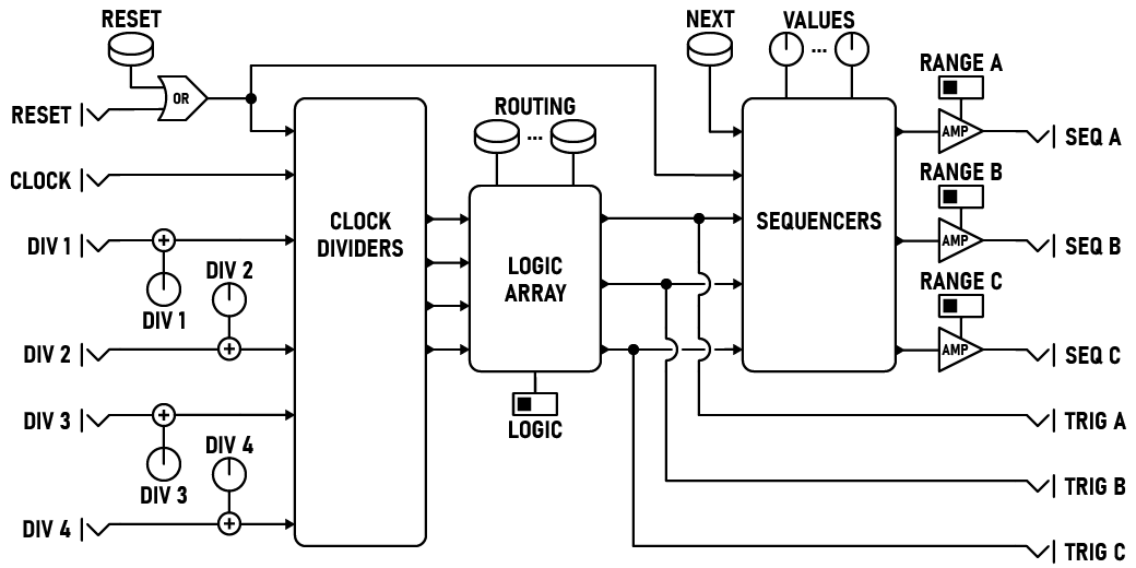
The PolyRhythm Sequencer uses four simultaneous rhythm dividers to create complex, interweaving polyrhythms. Each divider creates a new rhythm by dividing incoming clock pulses by integer values. These pulses are combined in the routing matrix to advance the three sequencer tracks.

When connecting multiple rhythm dividers in the same column, each different rhythm combines to synthesize a complex, evolving polyrhythm. As each component re-synchronizes, the overall rhythm repeats. Each rhythm divider can be rerouted, modulated, and shifted as you perform, creating deep melodies and grooves.

Parameters

  • DIV [N] Knobs

    Sets the number of clock pulses between rhythm divider pulses, from 1 to 16.

  • ROUTING Buttons

    Routes pulses from the four rhythm dividers to the three sequencer tracks. If multiple dividers are connected to the same tracks, they are combined according to the LOGIC switch.

  • VALUE Knobs

    Sets the value of each sequencer step. The actual voltage outputs are determined by the RANGE switches.

  • RESET Button

    Resets all sequencer tracks and rhythm divider counts to their initial states.

  • NEXT Button

    Advances all three sequencer tracks by one step, and outputs triggers on all three TRIG outputs.

  • LOGIC Switch

    Changes the logic used to combine multiple rhythm dividers when advancing each sequencer track. When set to OR, the sequencer track advances if any of the connected rhythm dividers are triggered. When set to XOR, the track only advances if an odd number of dividers trigger at the same time.

  • RANGE Switches

    Selects the voltage range output by each sequencer track, selectable as ±1 V, ±2 V, or ±5 V.

Ports

  • CLOCK Input

    Accepts clock pulses that drive each rhythm divider.

    TRIGGER INPUT: 0V to +10V (rising edge)

  • RESET Input

    A trigger received here resets all sequencer tracks and rhythm dividers to their initial states. When the input is held high, the rhythm dividers continue to trigger and output pulses from the three TRIG outputs, but do not advance sequencer tracks. In this state, the NEXT button advances each sequencer to the next step. Normal playback resumes once the gate signal ends.

    TRIGGER INPUT: 0V to +10V (rising edge trigger, gate)

  • DIV [N] Inputs

    Connect control voltages here to modulate the division used by each rhythm divider. The value of these inputs are summed with the DIV [N] knobs before use; the knobs should be set at 50% to modulate over the full control range.

    CV INPUT: -5V to +5V

  • TRIG [X] Outputs

    Outputs a trigger when each sequencer track is advanced.

    TRIGGER OUTPUT: 0V to +10V

  • SEQ [X] Outputs

    Outputs the value of each sequencer track's current step. The exact voltage is dependent on the value of the RANGE switches.

    CV OUTPUT: -5V to +5V

Context Menu

Context menu options can be accessed by right-clicking on the module.

  • Randomize Dividers

    Sets each divider to a random value.

  • Randomize Grid

    Randomizes the routing grid.

  • Sequence [N]

    • Randomize

      Sets each step in the selected sequence to a random value.

    • Copy portable sequence

      Copies the contents of the selected sequence to the clipboard in Portable Sequence Format. Can be used to copy values between sequencer tracks, or between other compatible sequencer modules.

    • Paste portable sequence

      Pastes the contents of the clipboard to the selected sequence, if the clipboard contains a Portable Sequence.

  • State

    • Save state

      Saves the current state of all sequencer tracks and rhythm dividers. Use this to capture interesting states and return to them later.

    • Restore state

      Restores the most recent saved state of all sequencer tracks and rhythm dividers.

    • Reset restores state

      If set, resetting the module using either the RESET button or the RESET input restores the sequencer tracks and rhythm dividers to the most resent saved state, instead of clearing them.

Signal Flow Diagram

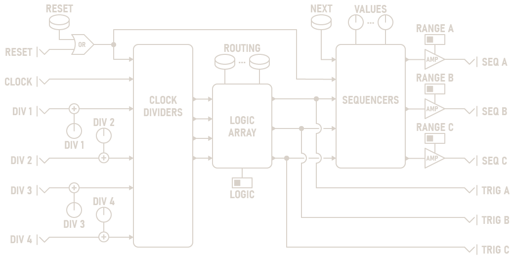
PolyRhythm Sequencer Diagram PolyRhythm Sequencer Diagram
Quantizer Outline Quantizer Outline

Description

The Quantizer takes in a continuous pitch and adjusts it to match a musical scale. Using a quantizer, you can ensure that an oscillator will harmonize with other tonal instruments. This module can quantize using more than three dozen different scales, depending on your chosen scale degree, temperament, and root.

While the ROOT knob specifies the root of a major scale, this module can also be used to quantize to minor scales. To use a minor scale, set the root to the scale's relative major scale, e.g. to use A minor, set the root to C.

In EQUAL Temperament mode, input is quantized to either a chromatic (12-step) scale or one of twelve different diatonic (8-step, major) scales. These scales use the standard equal temperament tuning used by most modern instruments, where all semitones are exactly 100 cents apart.

In JUST Intonation mode, the quantizer uses an alternate tuning based on integer ratios instead: C=1⁄1, G=3⁄2, F=4⁄3, etc. Because this temperament uses whole number fractions, any subharmonics generated by the Sub-Oscillator module will sound more in-tune.

Note: A 5-limit asymmetric chromatic extension of Ptolemy's intense diatonic scale was used to construct this scale. Notes differ from equal temperament by up to 18 cents depending on the root note.

Parameters

  • TEMPERAMENT Switch

    Switches between just intonation and equal temperament.

  • SCALE DEGREE Switch

    Set the scale degree to quantize to. When set to DIATONIC, an eight-note major scale is used; when set to CHROMATIC, a twelve-tone chromatic scale is used.

  • ROOT Knob

    Set the root note of the quantization scale. This ordinarily represents the root of a major scale. To use a minor scale, set the root to the scale's relative major scale, e.g. to use A minor, set the root to C.

    Note: This knob has no effect when TEMPERAMENT is set to EQUAL and SCALE DEGREE is set to CHROMATIC.

  • TRANS Button

    If set, transposes the quantized note so that 0V corresponds to the root note set by the ROOT knob.

  • OCT Knob

    Transposes the quantized note up or down by an octave, from -4 to +4 octaves.

Ports

  • ROOT Input

    Modifies the scale root using a 1-volt/octave pitch. Only the fractional (that is, after the decimal point) part of the voltage is used; the octave is ignored. To use a specific note and octave in conjunction, connect the ROOT and OCTAVE inputs to the same source.

    V/OCT INPUT: -5V to +5V

  • OCT Input

    Adds or subtracts octaves from the output using a 1-volt/octave pitch. Only the integral (that is, before the decimal point) part of the voltage is used; the note is ignored. To use a specific note and octave in conjunction, connect the ROOT and OCTAVE inputs to the same source.

    V/OCT INPUT: -5V to +5V

  • IN Polyphonic Input

    Accepts a 1-volt/octave pitch to quantize.

    V/OCT INPUT: -5V to +5V, Polyphonic

  • OUT Polyphonic Output

    Outputs the quantized pitch.

    V/OCT OUTPUT: -5V to +5V, Polyphonic

Context Menu

Context menu options can be accessed by right-clicking on the module.

  • Scale

    Configure the type of scale used for quantizing and transposing: Major or Natural Minor.

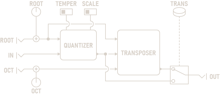
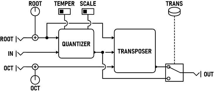
Signal Flow Diagram

Quantizer Diagram Quantizer Diagram
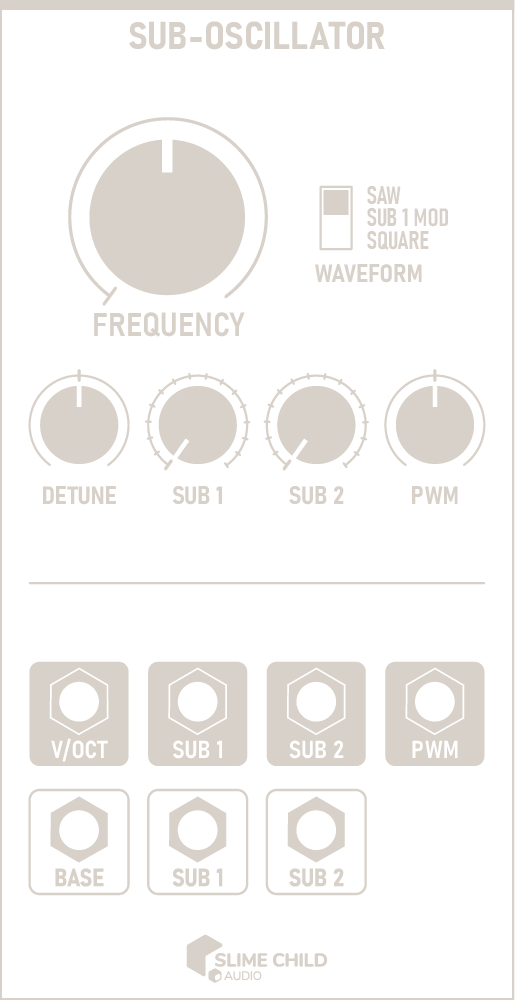
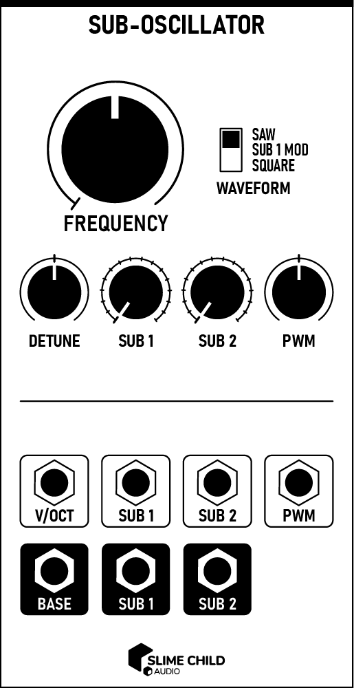
Sub-Oscillator Outline Sub-Oscillator Outline

Description

The Sub-Oscillator features three linked oscillators with configurable waveforms. The main oscillator tracks the V/OCT input, while the two sub-oscillators synthesize subharmonics of the base waveform. Subharmonics are produced by dividing the base frequency by an integer value. By carefully tuning the two sub-oscillators, you can create moving chords and underlying bass melodies.

Parameters

  • FREQUENCY Knob

    This knob controls the initial pitch at 0V. It ranges from C0 (16.35 Hz) to C8 (4186 Hz), slightly wider than the range on a standard 88-key piano. The default value of 261.63 Hz corresponds to Middle C.

  • WAVEFORM Switch

    This switch configures the waveform generated by each oscillator. See the chart at the end of this section for more information.

  • DETUNE Knob

    This knob slightly detunes each subharmonic oscillator in relation to the base frequency, by up to 2 Hz (or 20 cents if in cents mode). A positive detune amount increases SUB 1's frequency and decreases SUB 2's frequency. Negative detune amounts do the reverse.

    Adding a small amount of detune creates appealing chorus and phasing effects, and is recommended when using the SUB 1 MOD waveform.

    Using the context menu, you can configure this knob to operate using either Hz or cents. When using cents mode, the exact detune amount is dependent on the absolute frequency of each oscillator.

  • SUB [N] Knobs

    These knobs select each subharmonic oscillator's frequency division. At 1, the oscillator generates the same frequency; at 16, the oscillator generates a waveform four octaves lower than the base.

  • PWM Knob

    This knob modifies the pulse width of each square-wave oscillator, from 10% to 90%.

Ports

  • V/OCT Input

    This input accepts a 1-volt/octave control signal and sets the base pitch of all oscillators. The frequency corresponding to 0V is set using the FREQUENCY knob.

    V/OCT INPUT: -5V to +5V

  • SUB [N] Inputs

    Control voltage here modulates the selected subharmonic for each subharmonic oscillator. The value of these inputs are summed with the SUB [N] knobs before use; the knobs should be set at 50% to modulate over the full control range.

    CV INPUT: -5V to +5V

  • PWM Input

    Control voltage here modulates the pulse width of all three square-wave oscillators. The value of this input is summed with the PWM knob before use; the knob should be set at 50% to modulate over the full control range.

    CV INPUT: -5V to +5V

    Note: Pulse width of 10% to 90% is possible

  • BASE Output

    The output of the main oscillator. See the chart below for information on how the WAVEFORM switch affects the waveform. AC-coupled.

    AUDIO OUTPUT: -5V to +5V

  • SUB [N] Outputs

    The outputs of each subharmonic oscillator. See the chart below for information on how the WAVEFORM switch affects the waveform. AC-coupled.

    AUDIO OUTPUT: -5V to +5V

Waveform Selection

WAVEFORM BASE SUB 1 SUB 2
SAW Saw Saw Saw
SUB 1 MOD Square (PWM + SUB 1) Saw Saw
SQUARE Square (PWM) Square (PWM) Square (PWM)

Context Menu

Context menu options can be accessed by right-clicking on the module.

  • Detune in cents

    If checked, the DETUNE knob uses cents instead of Hz. This makes the exact detune amount dependent on the absolute frequency of each oscillator.

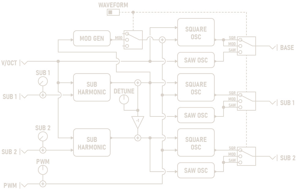
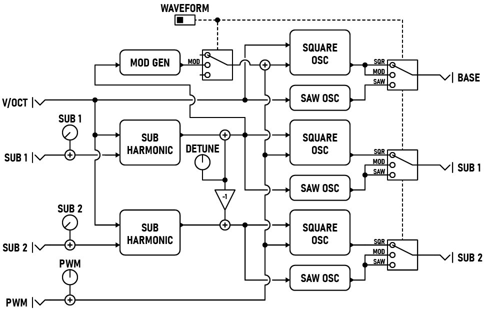
Signal Flow Diagram

Sub-Oscillator Diagram Sub-Oscillator Diagram
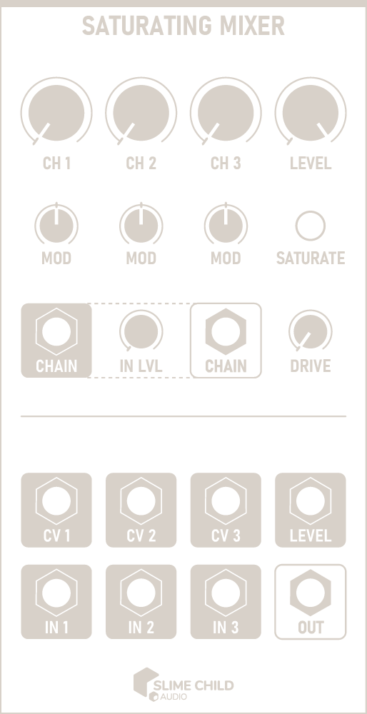
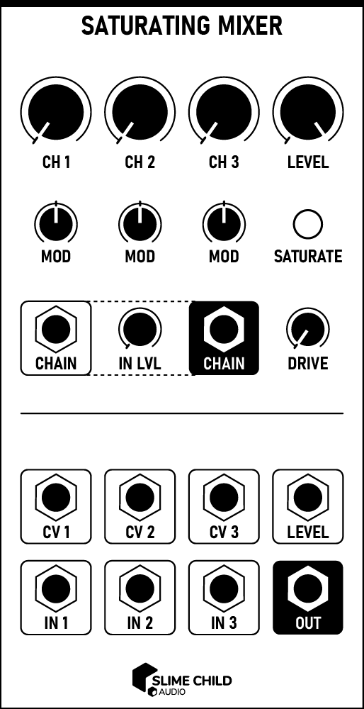
Saturating Mixer Outline Saturating Mixer Outline

Description

The Saturating Mixer is a a chainable, CV-controllable three-channel mixer with drive and saturation.

The mixer is a summing mixer, not a unity mixer, so setting each channel to 100% will result in a very hot signal with some warm distortion. In some cases this is desirable, but for a cleaner sound, reduce each channel's incoming level to moderate levels. The SATURATE indicator is used to monitor the amount of saturation / drive occurring.

Parameters

  • CH [N] Knobs

    Sets the level of each incoming channel, from 0% to 100%.

  • MOD Knobs

    Scales the effect of the CV [N] inputs, from -100% to +100%.

  • IN LVL Knob

    Sets the input gain of the CHAIN input, from 0% to 100%.

  • DRIVE Knob

    Applies additional drive to the mixed signal before saturation, creating symmetric distortion that creates odd harmonics. This control sits before the saturation circuit.

  • LEVEL Knob

    Sets the overall output level of the mixer, from 0% to 100%. This control sits after the saturation circuit.

Ports

  • IN [N] Inputs

    The input signals to the mixer.

    AUDIO INPUT: -5V to +5V

  • CV [N] Inputs

    Modulation voltages that affect the level of each channel. When MOD is set to 100%, 1V at this input adds 10% to the relevant channel level.

    CV INPUT: -5V to +5V

  • CHAIN Input

    Accepts voltage from another mixer's CHAIN output, allowing mixer modules to be chained to increase the total number of channels available.

    AUDIO INPUT: -5V to +5V

  • CHAIN Output

    The raw mixer output voltage, which is not affected by the drive, saturation, or level circuits.

    Use this output, along with its corresponding input, to increase the total number of channels available.

    AUDIO OUTPUT: -5V to +5V

  • LEVEL Input

    Modulates the LEVEL knob. 1V at this input corresponds to a change of 10%.

    CV INPUT: -5V to +5V

  • OUT Output

    The mixer's output voltage, after passing through the drive, saturation, and level circuits.

    AUDIO OUTPUT: -5V to +5V

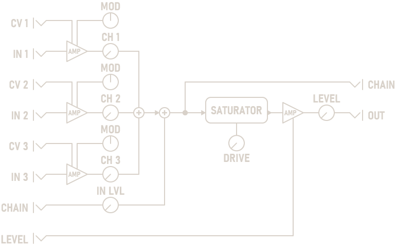
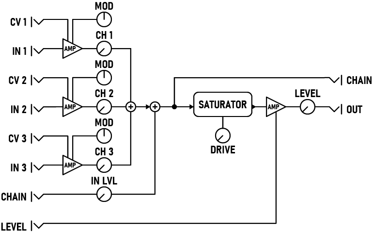
Signal Flow Diagram

Saturating Mixer Diagram Saturating Mixer Diagram
Envelopes Outline Envelopes Outline

Description

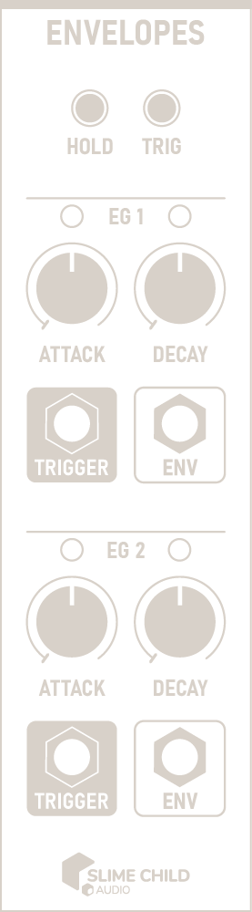
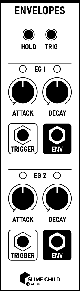
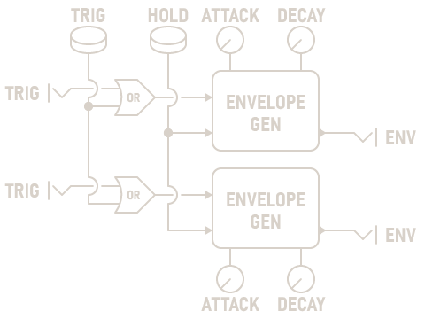
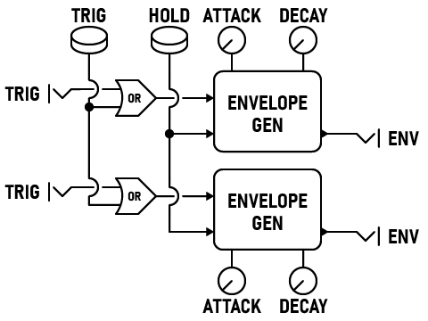
The Envelopes module is a pair of exponential Attack-Decay envelopes that are used to modulate parameters.

When a trigger is received, the envelope generator gradually rises from 0V to +10V over the course of the Attack phase. When this is complete, the level falls back to 0V in the Decay phase, then idles.

Unlike other envelope generators, this module is unique in that the generator does not restart while in the Attack phase. Triggers are only processed while the generator is in the Decay or Idle phases. This creates additional poly-rhythmic effects: by carefully tuning the Attack time, close-together triggers are ignored.

Parameters

  • HOLD Button

    Holds both envelopes at their maximum value, for tuning modulation amounts.

  • TRIG Button

    Triggers both envelopes.

  • ATTACK Knobs

    Sets the amount of time the envelope takes to rise from 0V to +10V, with a range of 1ms to 10s. this knob spans four decades; hold the CTRL key for fine adjustments.

  • DECAY Knobs

    Sets the amount of time the envelope takes to from from +10 to +0V, with a range of 1ms to 10s. This knob spans four decades; hold the CTRL key for fine adjustments.

Ports

  • TRIGGER Inputs

    Triggers each envelope generator.

    TRIGGER INPUT: 0V to +10V (rising edge)

    Note: Each envelope generator cannot be re-triggered in the Attack phase.

  • ENV Outputs

    The out of each envelope generator.

    CV OUTPUT: 0V to +10V

Signal Flow Diagram

Envelopes Diagram Envelopes Diagram
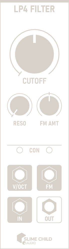
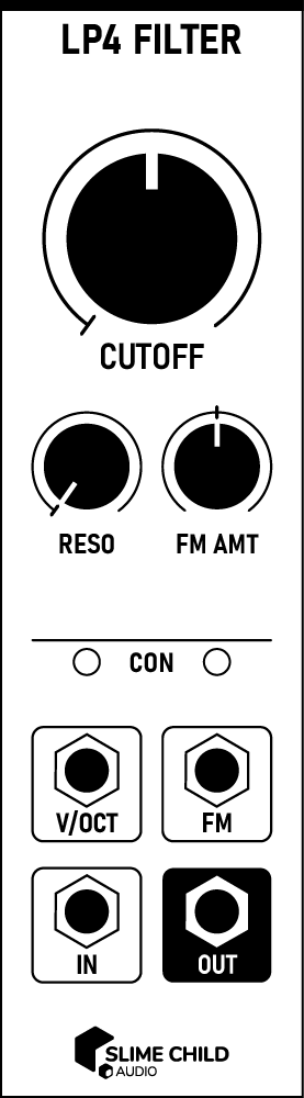
LP4 Filter Outline LP4 Filter Outline

Description

The LP4 Filter is a non-linear four-pole low-pass filter with 24 dB per octave attenuation. It can dynamically shape sounds and pick out individual harmonics, or act as a sine oscillator.

For additional functionality, add a Filter+ to either side of this module. If two expanders are present, their inputs are summed and their outputs are duplicated.

Parameters

  • CUTOFF Knob

    Sets the filter's cutoff frequency, from 20 Hz to 20k Hz. Increasing the cutoff results in a bright and buzzy sound, while decreasing it results in a dark and thick sound.

    When using the filter as a sine oscillator, set this knob to 261.63 Hz (Middle C) and use the V/OCT input to change the pitch.

  • RESO Knob

    Sets the filter's resonance, from 0% to 120%. Increasing the resonance allows some of the filter's output to be shaped and routed back to the input. This creates a resonant peak that emphasizes the cutoff frequency.

    Pushing the resonance beyond 100% causes the filter to self-oscillate, producing a pure sine tone at the cutoff frequency. In some cases, it can also create "half-harmonics" that lie between an input signal's existing harmonics.

  • FM AMT Knob

    Modulates the effect of the FM input, from -100% to +100%.

    At 0%, FM has no effect. At +100%, FM's value is added to IN. At -100%, its value is subtracted.

Ports

  • V/OCT Polyphonic Input

    Accepts a 1-volt/octave control signal that sets the filter cutoff. The CUTOFF knob sets the frequency corresponding to 0V.

    V/OCT INPUT: -5V to +5V

  • FM Polyphonic Input

    Modifies the filter's cutoff frequency. Connect the FM input to one of the ENV outputs on Envelopes to shape sounds, or to an LFO to slowly modulate the cutoff frequency.

    CV INPUT: -5V to +5V

    Note: Value is added to V/OCT after passing through FM AMT; exponential response.

  • IN Polyphonic Input

    The input signal.

    AUDIO INPUT: -5V to +5V

  • OUT Polyphonic Output

    The output signal after passing through the filter.

    AUDIO OUTPUT: -5V to +5V

Context Menu

Context menu options can be accessed by right-clicking on the module.

  • Quality

    Configure the filter quality level, between Default, High, and Extreme. When self-modulating resonance or cutoff, a higher quality level can help reduce distortion. In most cases, the difference between these levels is not audible, and this setting can be left at Default. Note that higher quality levels will use more CPU.
  • Add expander (right, 4HP)

    Adds an instance of Filter+ to the right of this module.

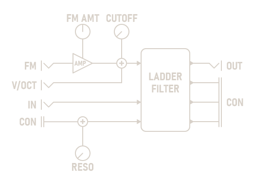
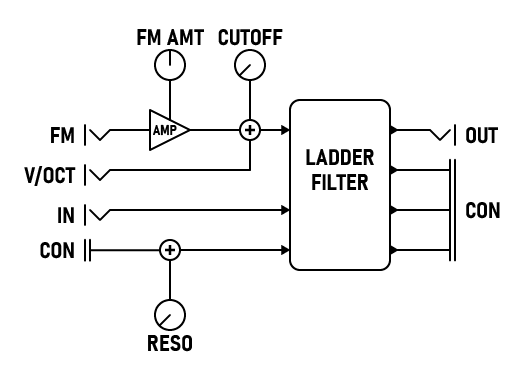
Signal Flow Diagram

LP4 Filter Diagram LP4 Filter Diagram
Filter+ Outline Filter+ Outline

Description

Filter+ is an expander module that adds additional functionality to the LP4 Filter. In order to use it, the module must be placed directly to the left or right of the filter, with no space in between. Lights will illuminate on both modules to indicate that a connection has been made.

This expander module can connect to one instance of the LP4 Filter on either the left or the right. If modules are present on both sides, the left is preferred.

Parameters

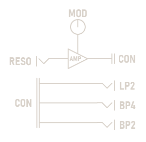
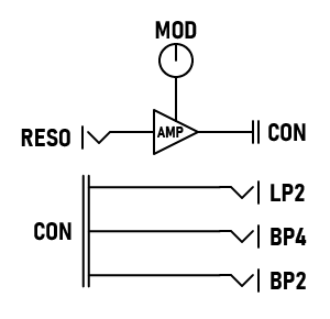
  • MOD Knob

    Scales the effect of the RESO input, from -100% to +100%.

Ports

  • RESO Polyphonic Input

    Modulates the connected filter's RESO parameter.

    CV INPUT: -5V to +5V

  • LP2 Polyphonic Output

    The output signal from a 2-pole lowpass filter.

    AUDIO OUTPUT: -5V to +5V

  • BP2 Polyphonic Output

    The output signal from a 2-pole bandpass filter.

    AUDIO OUTPUT: -5V to +5V

  • BP4 Polyphonic Output

    The output signal from a 4-pole bandpass filter.

    AUDIO OUTPUT: -5V to +5V

Signal Flow Diagram

Filter+ Diagram Filter+ Diagram
VCA Outline VCA Outline

Description

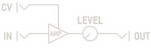
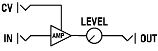
A standard linear voltage-controlled amplifier with CV level control, output level knob, and signal level meter.

Connect the CV input to one of the ENV outputs on Envelopes to shape sounds, or to an LFO to slowly modulate the level.

Parameters

  • LEVEL Knob

    Sets the overall output level of the amplifier, from 0% to 100%. Non-linear, roughly quadratic.

Ports

  • CV Input

    Linearly modulates the output level. 0V corresponds to 0% and +10V to 100%; negative voltages are treated as 0%, not inverted.

    CV INPUT: 0V to +10V

  • IN Polyphonic Input

    The input signal.

    CV / AUDIO INPUT: -5V to +5V

  • OUT Polyphonic Output

    The output signal, obtained by multiplying the input signal by the gain amount derived from the LEVEL knob and the CV input. Outputs the same number of polyphonic channels as IN.

    CV / AUDIO OUTPUT: -5V to +5V

Signal Flow Diagram

VCA Diagram VCA Diagram

Quadruped

by Slime Child Audio

Quadruped

Gateway

by Slime Child Audio

Gateway

Reminder

by Slime Child Audio

Reminder

Elements

by Slime Child Audio

Elements

Beginner

by Jeremy Wentworth

Beginner

Medium 2

by Jeremy Wentworth

Medium 2

Advanced

by Jeremy Wentworth

Advanced

Drone

by Jeremy Wentworth

Drone

Medium 1

by Jeremy Wentworth

Medium 1

Medium 3

by Jeremy Wentworth

Medium 3

Drums

by Jeremy Wentworth

Drums

Found a bug? Not sure how a module works? Need help bringing your creative vision to life? Have an idea for a new feature? Want to show us what you've made? Just want to chat? Feel free to Contact Us and we'll help you out!

Substation for VCV Rack was created by Coriander V. Pines, dba Slime Child Audio. All designs, user interfaces, software implementations, and supplementary material are copyright © 2020 Coriander V. Pines. All rights reserved.

Substation would not exist without the generous work of Andrew Belt and the rest of the VCV team. Support VCV Rack development by purchasing this product through the VCV Library.

I am hugely grateful for the members of the VCV Rack community who were kind enough offer their help and support during development, particularly:

I owe the mathematical foundations of this plugin to Stefano D’Angelo, Vesa Välimäki, Jussi Pekonen, Victor Lazzarini, Joseph Timoney, Jari Kleimola, Antti Huovilainen, Paolo Prandoni, and Martin Vetterli. Thank you for making your research available to all, free of cost.

Additional thanks to Lauren Merriman for her support while I took this plugin from concept to prototype to publication. I couldn't have done it without you.

Substation v2.2.6

Released 2023-10-19

v2.2.6 adds support for Mac ARM64, and marks the end of the support window.

  • Added support for Mac ARM64 builds
  • Updated to Rack SDK 2.4.1
  • Various small performance improvements and bug fixes

Substation v2.2.5

Released 2022-10-07

v2.2.5 includes some minor bug fixes and performance improvements.

  • Fixed bug where Filter+ failed to respond to polyphonic inputs
  • Improved performance and error handling
  • Updated to Rack SDK 2.1.4

Substation v2.2.4

Released 2022-01-09

v2.2.4 includes some minor bug fixes and performance improvements.


Substation v2.2.3

Released 2021-11-30

v2.2.3 provides support for the public release of VCV Rack 2.0 (Free and Pro).

  • Adds full support for the public release of Rack 2.0, including DAW integration
  • Improves the appearance of buttons in dark mode

Substation v2.2.2 (Preview Release)

Released 2021-11-27

v2.2.2 adds experimental support for VCV Rack 2.0 (Free and Pro), along with some new features commonly requested by users.

  • Added experimental support for preview versions of Rack 2.0, including DAW integration
  • Added context menu option to Quantizer that allows selecting between Major and Natural Minor scales
  • Added context menu option to Sub-Oscillator that allows selecting between detuning in Hz and cents.
  • Added two additional filter quality modes to LP4 Filter
  • Added fingerprints and smudges to all knobs
  • Added support for room brightness dimming
  • Reduced plugin size for faster installs
  • Reduced plugin memory usage
  • Various bugfixes and performance improvements in all modules

Substation v1.2.1

Released 2021-02-28

The first update to Substation, v1.2.1 adds a new expander module providing more filter functionality, additional sequence management tools for PolySeq, and some general quality-of-life improvements.

  • Added new Filter+ module:
    • Expander module for LP4 Filter
    • Allows CV control of filter resonance
    • Adds additional filter types: 2-pole lowpass, 4-pole bandpass, 2-pole bandpass
  • Added new sequence management features to PolyRhythm Sequencer:
    • Added options to context menu for saving and restoring state
    • Added option to context menu to make reset button restore saved state
    • Implemented portable sequence format
    • Reorganized context menu
  • UI changes to LP4 Filter:
    • Added indicators that display connection to expander modules
    • Added context menu option for automatically adding an expander module
  • Added spacebar hotkey to Clock for stopping and starting clock.
  • Changed layout of VCA to better match other modules
  • Minor UI change to Quantizer
  • Various bugfixes and performance improvements in all modules

Substation v1.1.0

Released 2021-01-24

Initial public release!