Description
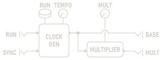
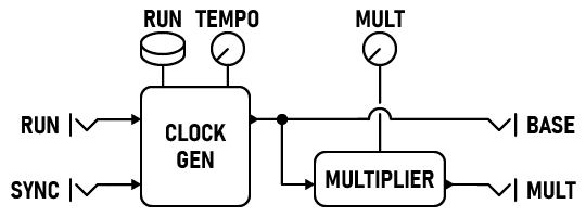
The Clock module generates regular pulses that can drive the Polyrhythm Sequencer or any other clocked module.
Parameters
-
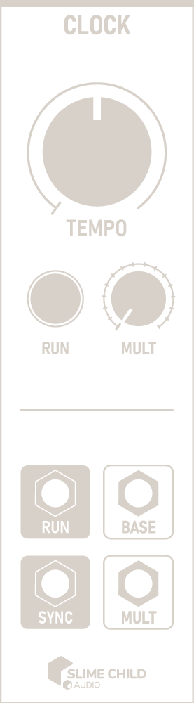
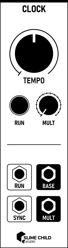
TEMPO Knob
This knob sets the base tempo from 20 BPM to 720 BPM or 0.33 Hz to 12 Hz.
-
Button
This button is used to start or stop the clock. When the RUN port is connected, the button automatically changes state to reflect it.
The spacebar can also be used to quickly start or stop the clock.
-
MULT Knob
This knob is used to generate a secondary, synced clock pulse at rate equal to the product of TEMPO and MULT. This is useful when clocking multiple modules: because the Polyrhythm Sequencer divides the clock rate, it is helpful to provide it a faster rate than other modules in a patch.
Ports
-
RUN Input
Signal transitions received here toggle the status of the button. A rising edge starts the clock, and a falling edge stops it. Pressing the button manually overrides the status.
GATE INPUT: 0V to +10V (rising edge, falling edge)
Note: Unlike other clock modules, gate value is not important; only transitions (rising, falling edges) toggle the clock status.
-
SYNC Input
A rising edge received here re-syncs the clock. Following a sync, both BASE and MULT reset to the beginning of a full pulse, starting HIGH.
This port is useful for syncing to other external clock modules. As long as the module receiving sync pulses has a tempo equal to or greater than the rate of incoming pulses, output pulses are synchronized.
TRIGGER INPUT: 0V to +10V (rising edge)
-
BASE Output
Clock pulses are output here at the un-multiplied tempo.
CLOCK OUTPUT: 0V to +10V
-
MULT Output
Clock pulses are output here at the multiplied tempo.
CLOCK OUTPUT: 0V to +10V