Description
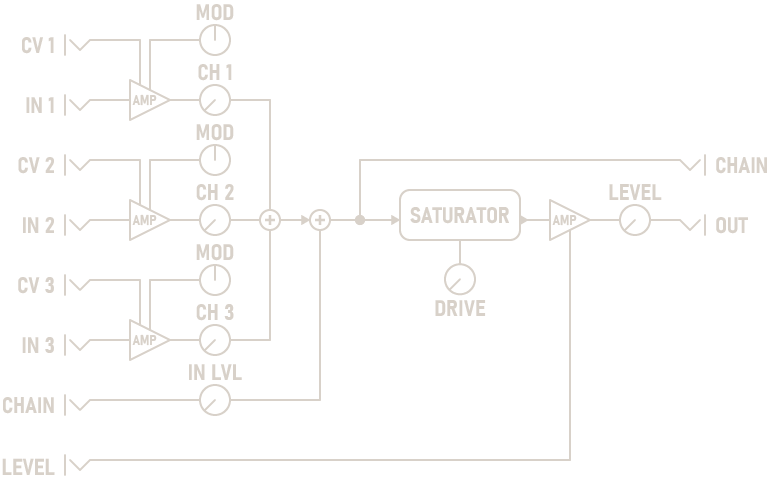
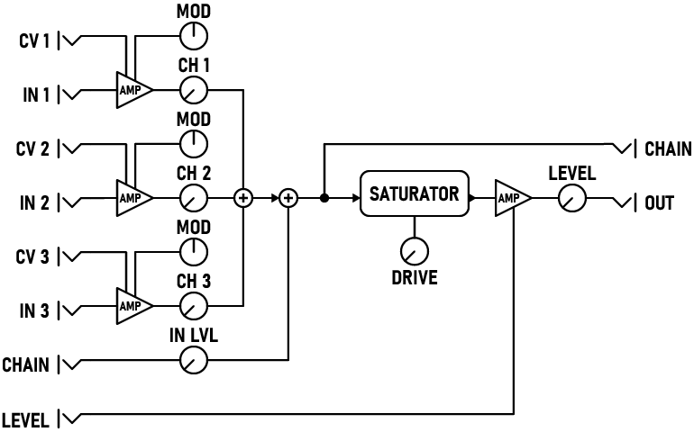
The Saturating Mixer is a a chainable, CV-controllable three-channel mixer with drive and saturation.
The mixer is a summing mixer, not a unity mixer, so setting each channel to 100% will result in a very hot signal with some warm distortion. In some cases this is desirable, but for a cleaner sound, reduce each channel's incoming level to moderate levels. The SATURATE indicator is used to monitor the amount of saturation / drive occurring.
Parameters
-
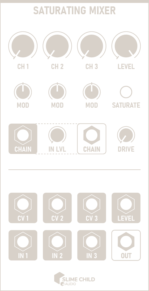
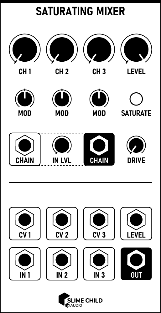
CH [N] Knobs
Sets the level of each incoming channel, from 0% to 100%.
-
MOD Knobs
Scales the effect of the CV [N] inputs, from -100% to +100%.
-
IN LVL Knob
Sets the input gain of the CHAIN input, from 0% to 100%.
-
DRIVE Knob
Applies additional drive to the mixed signal before saturation, creating symmetric distortion that creates odd harmonics. This control sits before the saturation circuit.
-
LEVEL Knob
Sets the overall output level of the mixer, from 0% to 100%. This control sits after the saturation circuit.
Ports
-
IN [N] Inputs
The input signals to the mixer.
AUDIO INPUT: -5V to +5V
-
CV [N] Inputs
Modulation voltages that affect the level of each channel. When MOD is set to 100%, 1V at this input adds 10% to the relevant channel level.
CV INPUT: -5V to +5V
-
CHAIN Input
Accepts voltage from another mixer's CHAIN output, allowing mixer modules to be chained to increase the total number of channels available.
AUDIO INPUT: -5V to +5V
-
CHAIN Output
The raw mixer output voltage, which is not affected by the drive, saturation, or level circuits.
Use this output, along with its corresponding input, to increase the total number of channels available.
AUDIO OUTPUT: -5V to +5V
-
LEVEL Input
Modulates the LEVEL knob. 1V at this input corresponds to a change of 10%.
CV INPUT: -5V to +5V
-
OUT Output
The mixer's output voltage, after passing through the drive, saturation, and level circuits.
AUDIO OUTPUT: -5V to +5V