Description
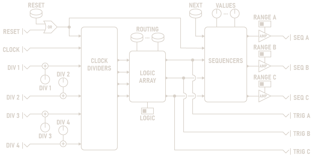
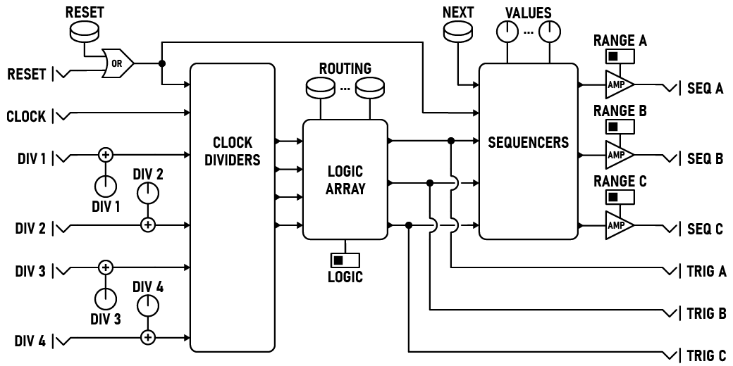
The PolyRhythm Sequencer uses four simultaneous rhythm dividers to create complex, interweaving polyrhythms. Each divider creates a new rhythm by dividing incoming clock pulses by integer values. These pulses are combined in the routing matrix to advance the three sequencer tracks.
When connecting multiple rhythm dividers in the same column, each different rhythm combines to synthesize a complex, evolving polyrhythm. As each component re-synchronizes, the overall rhythm repeats. Each rhythm divider can be rerouted, modulated, and shifted as you perform, creating deep melodies and grooves.
Parameters
-
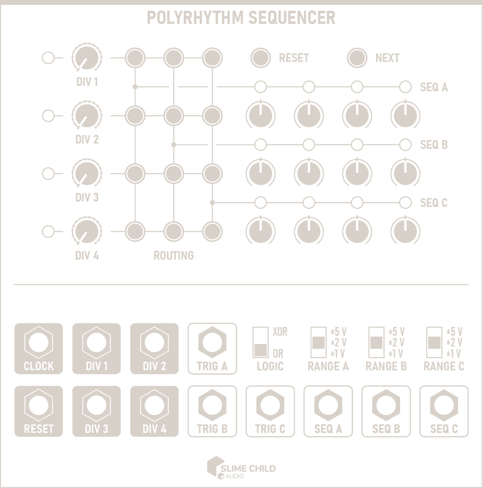
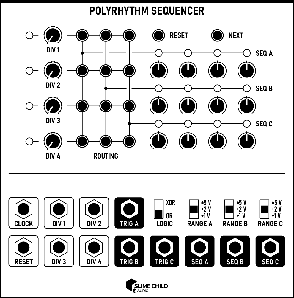
DIV [N] Knobs
Sets the number of clock pulses between rhythm divider pulses, from 1 to 16.
-
Buttons
Routes pulses from the four rhythm dividers to the three sequencer tracks. If multiple dividers are connected to the same tracks, they are combined according to the LOGIC switch.
-
VALUE Knobs
Sets the value of each sequencer step. The actual voltage outputs are determined by the RANGE switches.
-
Button
Resets all sequencer tracks and rhythm divider counts to their initial states.
-
Button
Advances all three sequencer tracks by one step, and outputs triggers on all three TRIG outputs.
-
LOGIC Switch
Changes the logic used to combine multiple rhythm dividers when advancing each sequencer track. When set to OR, the sequencer track advances if any of the connected rhythm dividers are triggered. When set to XOR, the track only advances if an odd number of dividers trigger at the same time.
-
RANGE Switches
Selects the voltage range output by each sequencer track, selectable as ±1 V, ±2 V, or ±5 V.
Ports
-
CLOCK Input
Accepts clock pulses that drive each rhythm divider.
TRIGGER INPUT: 0V to +10V (rising edge)
-
RESET Input
A trigger received here resets all sequencer tracks and rhythm dividers to their initial states. When the input is held high, the rhythm dividers continue to trigger and output pulses from the three TRIG outputs, but do not advance sequencer tracks. In this state, the button advances each sequencer to the next step. Normal playback resumes once the gate signal ends.
TRIGGER INPUT: 0V to +10V (rising edge trigger, gate)
-
DIV [N] Inputs
Connect control voltages here to modulate the division used by each rhythm divider. The value of these inputs are summed with the DIV [N] knobs before use; the knobs should be set at 50% to modulate over the full control range.
CV INPUT: -5V to +5V
-
TRIG [X] Outputs
Outputs a trigger when each sequencer track is advanced.
TRIGGER OUTPUT: 0V to +10V
-
SEQ [X] Outputs
Outputs the value of each sequencer track's current step. The exact voltage is dependent on the value of the RANGE switches.
CV OUTPUT: -5V to +5V
Context Menu
Context menu options can be accessed by right-clicking on the module.
-
Randomize Dividers
Sets each divider to a random value.
-
Randomize Grid
Randomizes the routing grid.
-
Sequence [N]
-
Randomize
Sets each step in the selected sequence to a random value.
-
Copy portable sequence
Copies the contents of the selected sequence to the clipboard in Portable Sequence Format. Can be used to copy values between sequencer tracks, or between other compatible sequencer modules.
-
Paste portable sequence
Pastes the contents of the clipboard to the selected sequence, if the clipboard contains a Portable Sequence.
-
-
State
-
Save state
Saves the current state of all sequencer tracks and rhythm dividers. Use this to capture interesting states and return to them later.
-
Restore state
Restores the most recent saved state of all sequencer tracks and rhythm dividers.
-
Reset restores state
If set, resetting the module using either the button or the RESET input restores the sequencer tracks and rhythm dividers to the most resent saved state, instead of clearing them.
-