Description
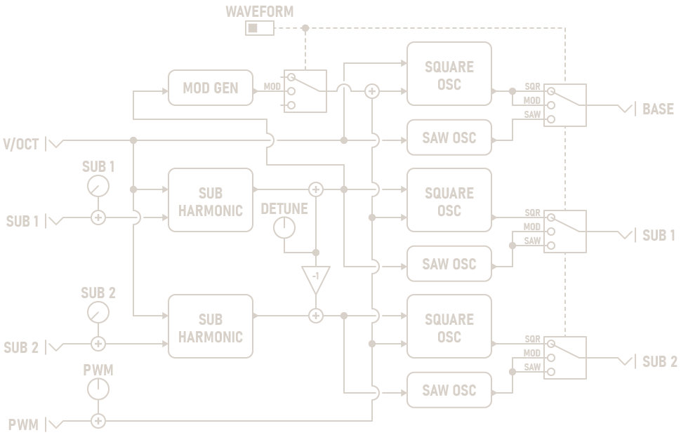
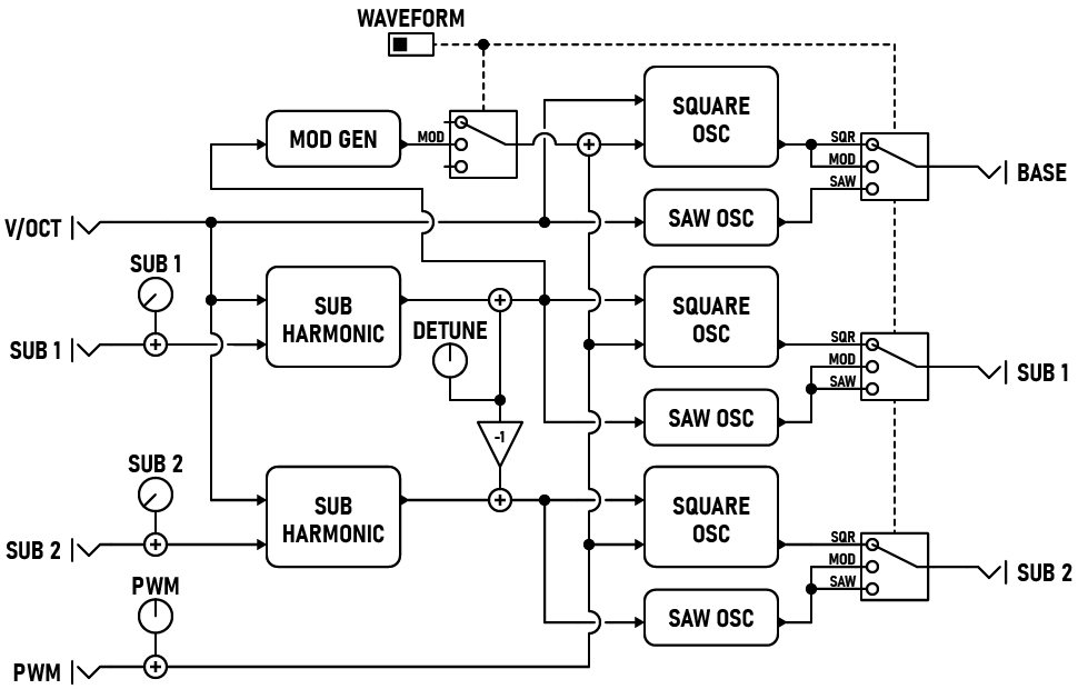
The Sub-Oscillator features three linked oscillators with configurable waveforms. The main oscillator tracks the V/OCT input, while the two sub-oscillators synthesize subharmonics of the base waveform. Subharmonics are produced by dividing the base frequency by an integer value. By carefully tuning the two sub-oscillators, you can create moving chords and underlying bass melodies.
Parameters
-
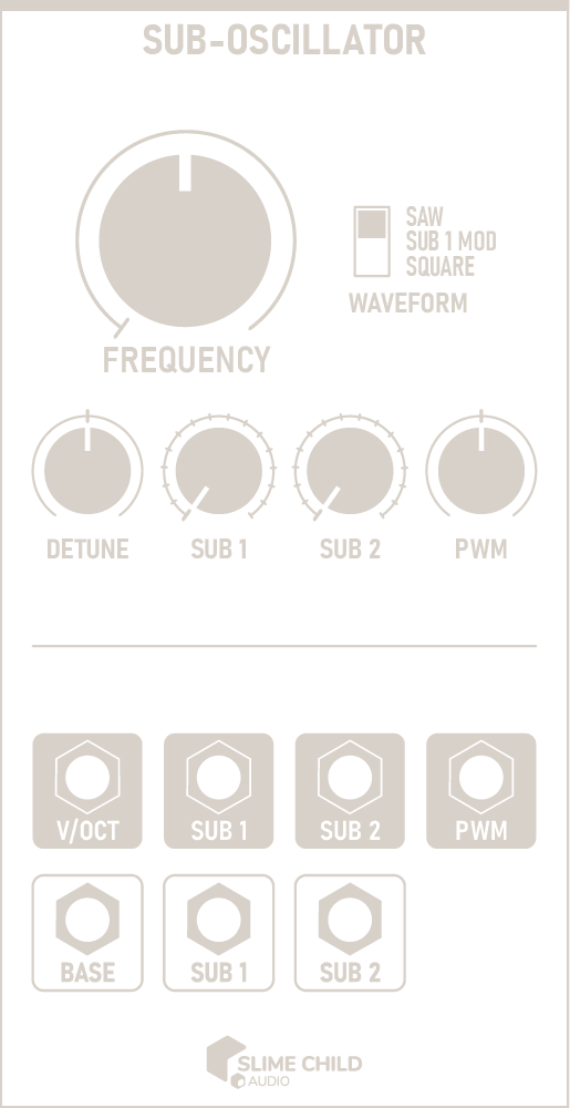
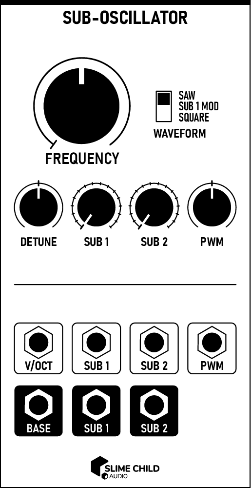
FREQUENCY Knob
This knob controls the initial pitch at 0V. It ranges from C0 (16.35 Hz) to C8 (4186 Hz), slightly wider than the range on a standard 88-key piano. The default value of 261.63 Hz corresponds to Middle C.
-
WAVEFORM Switch
This switch configures the waveform generated by each oscillator. See the chart at the end of this section for more information.
-
DETUNE Knob
This knob slightly detunes each subharmonic oscillator in relation to the base frequency, by up to 2 Hz (or 20 cents if in cents mode). A positive detune amount increases SUB 1's frequency and decreases SUB 2's frequency. Negative detune amounts do the reverse.
Adding a small amount of detune creates appealing chorus and phasing effects, and is recommended when using the SUB 1 MOD waveform.
Using the context menu, you can configure this knob to operate using either Hz or cents. When using cents mode, the exact detune amount is dependent on the absolute frequency of each oscillator.
-
SUB [N] Knobs
These knobs select each subharmonic oscillator's frequency division. At 1, the oscillator generates the same frequency; at 16, the oscillator generates a waveform four octaves lower than the base.
-
PWM Knob
This knob modifies the pulse width of each square-wave oscillator, from 10% to 90%.
Ports
-
V/OCT Input
This input accepts a 1-volt/octave control signal and sets the base pitch of all oscillators. The frequency corresponding to 0V is set using the FREQUENCY knob.
V/OCT INPUT: -5V to +5V
-
SUB [N] Inputs
Control voltage here modulates the selected subharmonic for each subharmonic oscillator. The value of these inputs are summed with the SUB [N] knobs before use; the knobs should be set at 50% to modulate over the full control range.
CV INPUT: -5V to +5V
-
PWM Input
Control voltage here modulates the pulse width of all three square-wave oscillators. The value of this input is summed with the PWM knob before use; the knob should be set at 50% to modulate over the full control range.
CV INPUT: -5V to +5V
Note: Pulse width of 10% to 90% is possible
-
BASE Output
The output of the main oscillator. See the chart below for information on how the WAVEFORM switch affects the waveform. AC-coupled.
AUDIO OUTPUT: -5V to +5V
-
SUB [N] Outputs
The outputs of each subharmonic oscillator. See the chart below for information on how the WAVEFORM switch affects the waveform. AC-coupled.
AUDIO OUTPUT: -5V to +5V
Waveform Selection
| WAVEFORM | BASE | SUB 1 | SUB 2 |
|---|---|---|---|
| SAW | Saw | Saw | Saw |
| SUB 1 MOD | Square (PWM + SUB 1) | Saw | Saw |
| SQUARE | Square (PWM) | Square (PWM) | Square (PWM) |
Context Menu
Context menu options can be accessed by right-clicking on the module.
-
Detune in cents
If checked, the DETUNE knob uses cents instead of Hz. This makes the exact detune amount dependent on the absolute frequency of each oscillator.